3D Mode System Modeling
Chamber Configuration
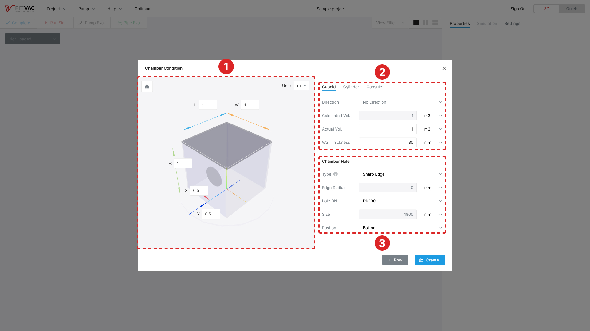
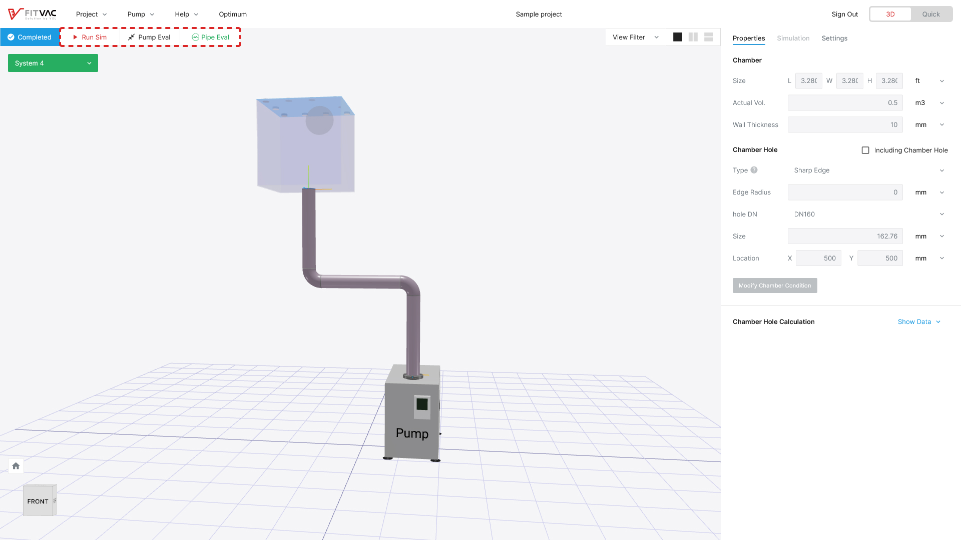
- Chamber size setting
- Setting of chamber size (L: length, W: width, H: height) & chamber hole position (x, y)
- The position of the chamber hole is set to the center of the face and can be changed
- Chamber setting
- Type: Select chamber type by shape (cuboid/cylinder/capsule)
- Calc. Vol.: Automatically calculated chamber volume
- Act. Vol.: Input the actual volume of chamber
- Wall Th.: Input the thickness of chamber wall (0.001 cm ≤ wall th. ≤ 10 cm)
- Chamber hole setting
- Select chamber hole type
- Round edge, sharp edge, through hole (default: sharp edge)
- Sharp edge & through hole: edge r. is automatically 0
- Edge R. Setting: Input edge radius when round edge is selected
- Range: 0 < Edge r. < t (t: thickness of chamber wall)
- Range: 0 < Edge r. < ID × 0.15 (ID: diameter of pipe)
- Hole DN & Size: Select hole standard
- Select DN standard or select "Custom" to input numerical data directly
- Position: Select the face where chamber hole is located (bottom/top/left/right/front/back)
- Select chamber hole type
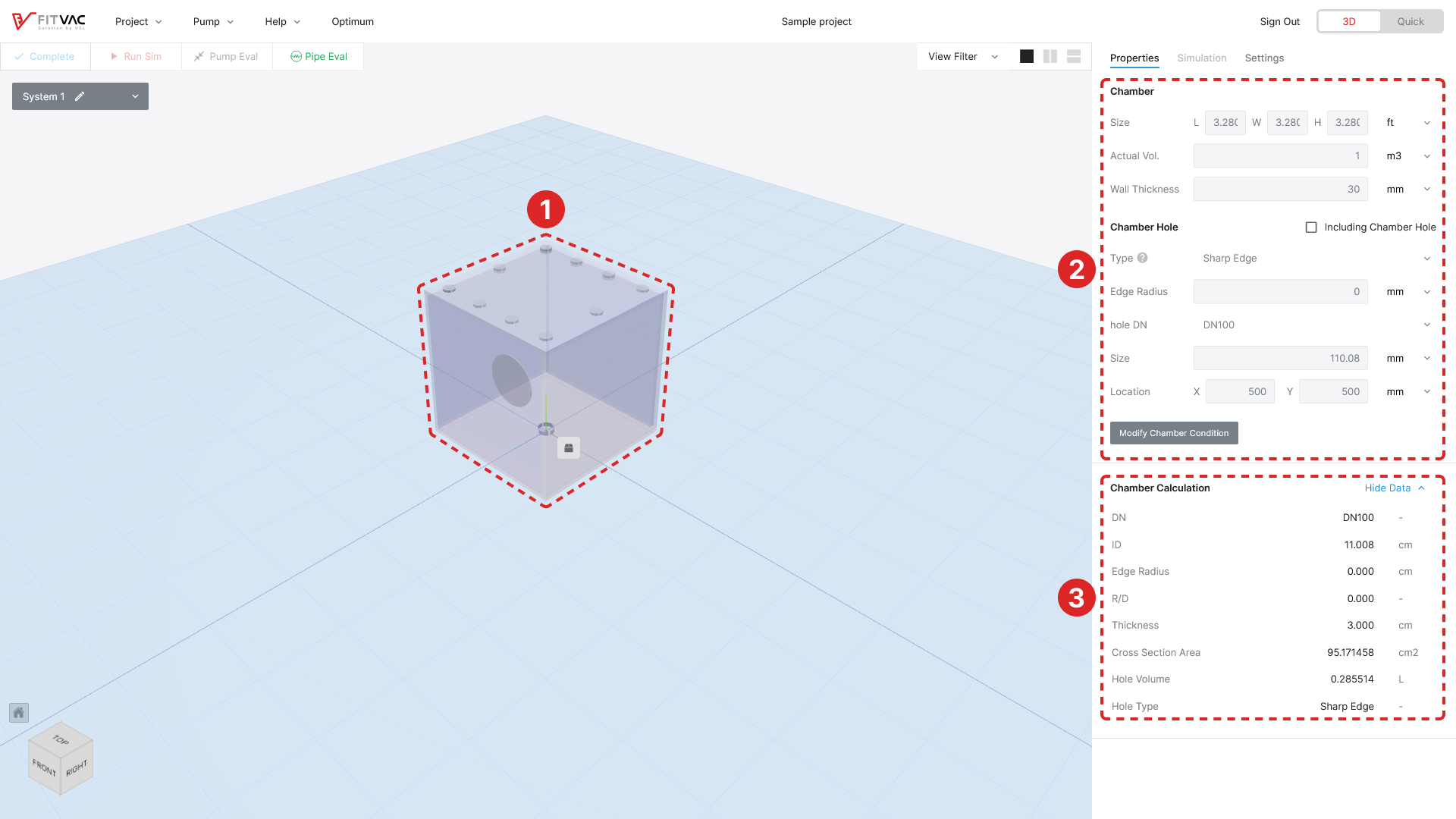
- Chamber modeling
- Chamber is displayed in the modeling area that user set in the chamber setting
- Chamber cannot be deleted
- Chamber property
- Chamber and chamber hole property values are displayed in the property window that user set in chamber setting
- Check the "Including Calculation" checkbox to include the value of the chamber hole into calculation and simulation
- Click the Modify Chamber Condition button to change the chamber settings
- Chamber hole property
- Click the "Show keyboard_arrow_down" to display the detailed property values for the chamber hole you entered when setting up the chamber
- Click the "Show keyboard_arrow_down" to display detailed property values for the chamber hole that user set in chamber setting
- The detailed property values of the chamber hole are automatically changed when changed in the project settings
Pipe Configuration
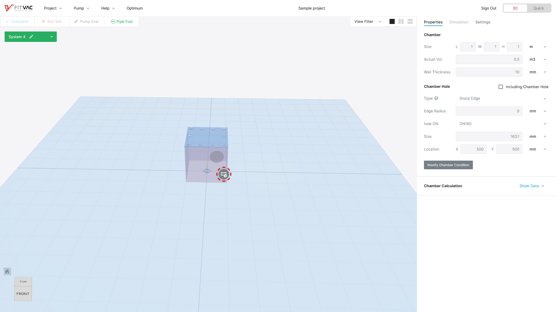
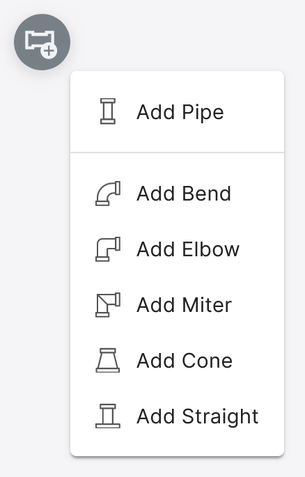
- Click the element menu button to connect element (pipe, bend/elbow/miter, and cone/straight) at modeling
- Depending on the selected modeling element, the following connectable modeling elements are changed
- Pipe ID is automatically set to the same ID of the previous element
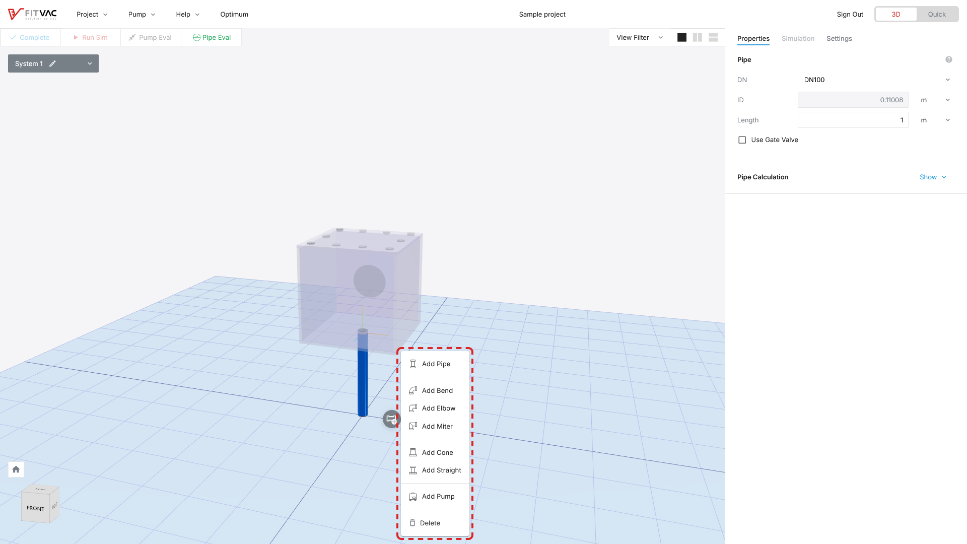
- Click the modeling element want to add
- Add Bend/Elbow/Miter: Add when changing the direction of pipe
- Add Cone/Straight: Add when changing pipe ID
- Add Pump: Add the pump to configured piping
- Delete: Delete modeling element (deleted backwards from the last element)
- Can also be deleted with the Delete key on your keyboard
Straight Tube
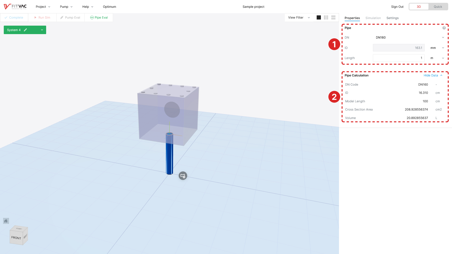
- Straight tube property
- ID: Automatically set to the same ID from previous element (chamber hole)
- Change ID: Select DN standard or select "custom" to input numerical data directly
- Length: Input the length of pipe (default: 1 m, 0.01 m ≤ pipe length ≤ 20 m)
- Use Gate Valve: Check when using the gate valve (Gate valve can only be added to Straight tube connected to the chamber directly)
- Valve Position: Input the location of gate valve → See Pipe Configuration – Valve
- help: Mouse over the icon to display the image of pipe and designation
- Straight tube detailed property
- Click the "Show keyboard_arrow_down" to display the pipe's detailed property values
- The detailed property values of the straight tube are automatically set when changed in the ①
Bend
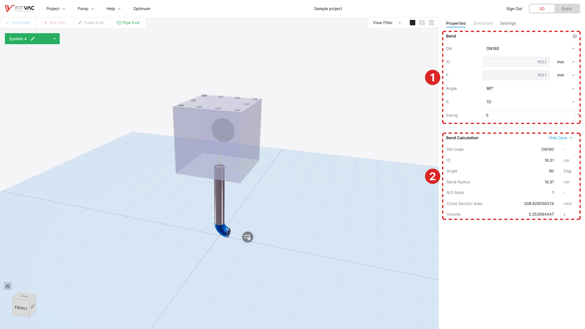
- Bend property
- ID: Automatically set to the same ID from previous element
- Change ID: Select DN standard or select "custom" to input numerical data directly
- Angle: Select the angle (30°/45°/60°/90°/custom, 1° ≤ custom angle ≤ 90°)
- R: Select the radius (1D/1.5D/2D/2.5D)
- Swing: Input the angle of the outlet direction (-360 < θ < 360)
- Bend can be replaced with the same angle of elbow or miter in modeling area (when pump connected)
- help: Mouse over the icon to display the image of bend and designation
- Bend detailed property
- Click the "Show keyboard_arrow_down" to display the bend's detailed property values
- The detailed property values of the bend are automatically set when changed in the ①
Elbow
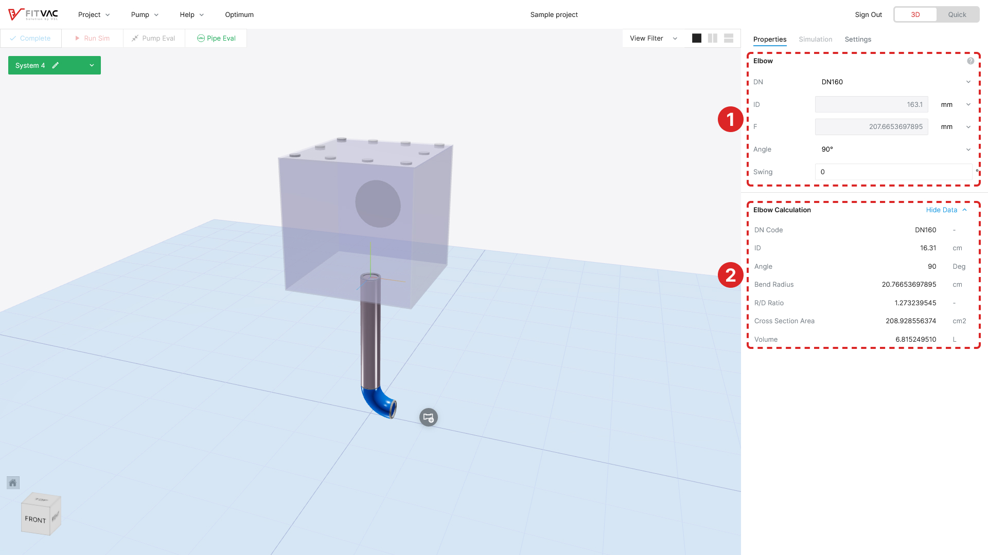
- Elbow property
- ID: Automatically set to the same ID from previous element
- Change ID: Select DN standard or select "custom" to input numerical data directly
- Angle: Select the angle (30°/45°/60°/90°/custom, 1° ≤ custom angle ≤ 90°)
- Swing: Input the angle of the outlet direction (-360 < θ < 360)
- Elbow can be replaced with the same angle of bend or miter in modeling area (when pump connected)
- help: Mouse over the icon to display the image of elbow and designation
- Elbow detailed property
- Click the "Show keyboard_arrow_down" to display the elbow's detailed property values
- The detailed property values of the elbow are automatically set when changed in the ①
Miter
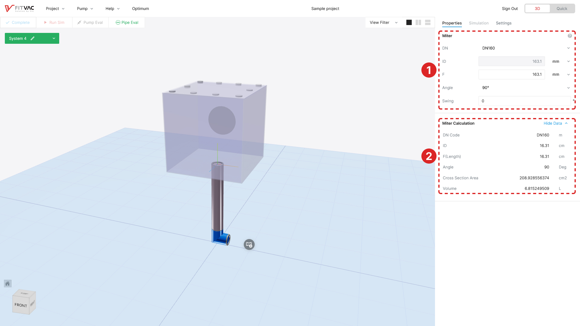
- Miter property
- ID: Automatically set to the same ID from previous element
- Change ID: Select DN standard or select "custom" to input numerical data directly
- F: Set to the same as the inlet ID
- Angle: Select the angle (30°/45°/60°/90°/custom, 1° ≤ custom angle ≤ 90°)
- Swing: Input the angle of the outlet direction (-360 < θ < 360)
- Miter can be replaced with the same angle of bend or elbow in modeling area (when pump connected)
- help: Mouse over the icon to display the image of miter and designation
- Miter detailed property
- Click the "Show keyboard_arrow_down" to display the miter's detailed property values
- The detailed property values of the miter are automatically set when changed in the ①
Reducer (Cone/Straight)
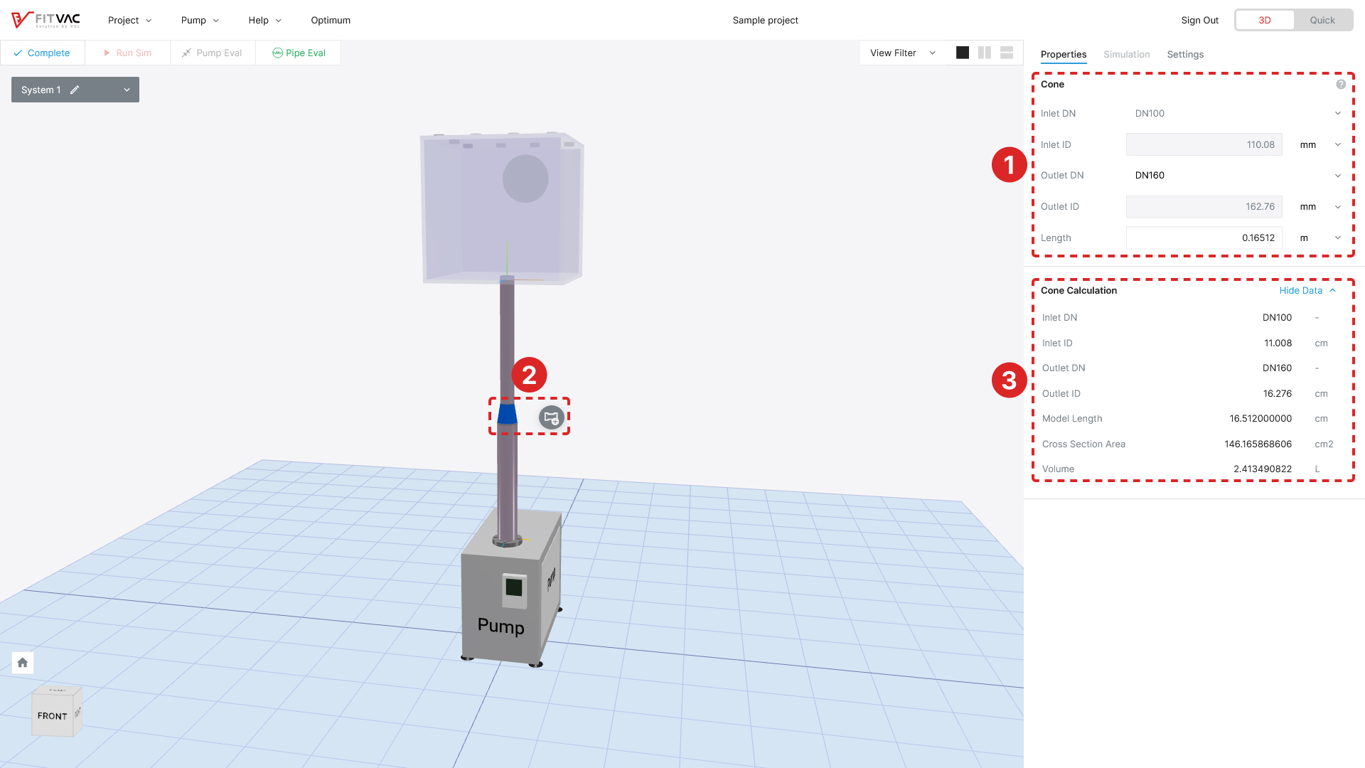
- Reducer property
- Inlet ID: Automatically set to the same ID from previous element
- Outlet ID: Automatically set to ID with size one step bigger than Inlet ID
- Change Inlet ID: Select DN standard or select "custom" to input numerical data directly
- Change Outlet ID: Select DN standard or select "custom" to input numerical data directly (Inlet ID and outlet ID cannot be the same size)
- Length: Input the length of cone and straight (default: L = 1.5 × ID1, 1 cm ≤ L ≤ 50 cm)
- ID1: Smaller ID of reducer between Outlet & Inlet
- help: Mouse over the icon to display the image of reducer and designation

Cone and straight are interchangeable in modeling area (when pump connected)- Reducer detailed property
- Click the "Show keyboard_arrow_down" to display the reducer's detailed property values
- The detailed property values of the reducer are automatically set when changed in the ①
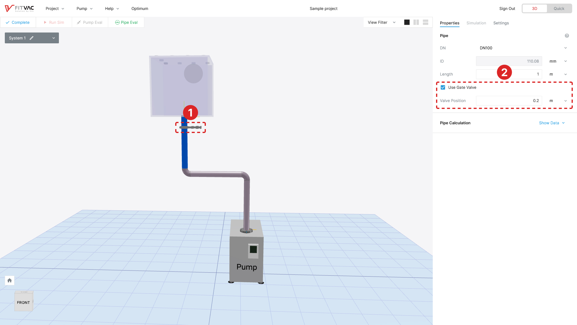
Valve (Gate/Angle)
- At the start of chamber pumping, when the valve is opened, the start pressure of chamber automatically set to equilibrium pressure
- Only one valve is possible per system regardless of valve type
- Gate valve configuration
- Check "Use Gate Valve" checkbox to configure gate valve in property window of straight tube connected to chamber
- Gate valve setting
- Input the gate valve position in straight tube (default: L × 1/5, L × 3/100 ≤ Position ≤ L × 100/100)
- L: Length of straight tube connected to chamber
- Input the gate valve position in straight tube (default: L × 1/5, L × 3/100 ≤ Position ≤ L × 100/100)
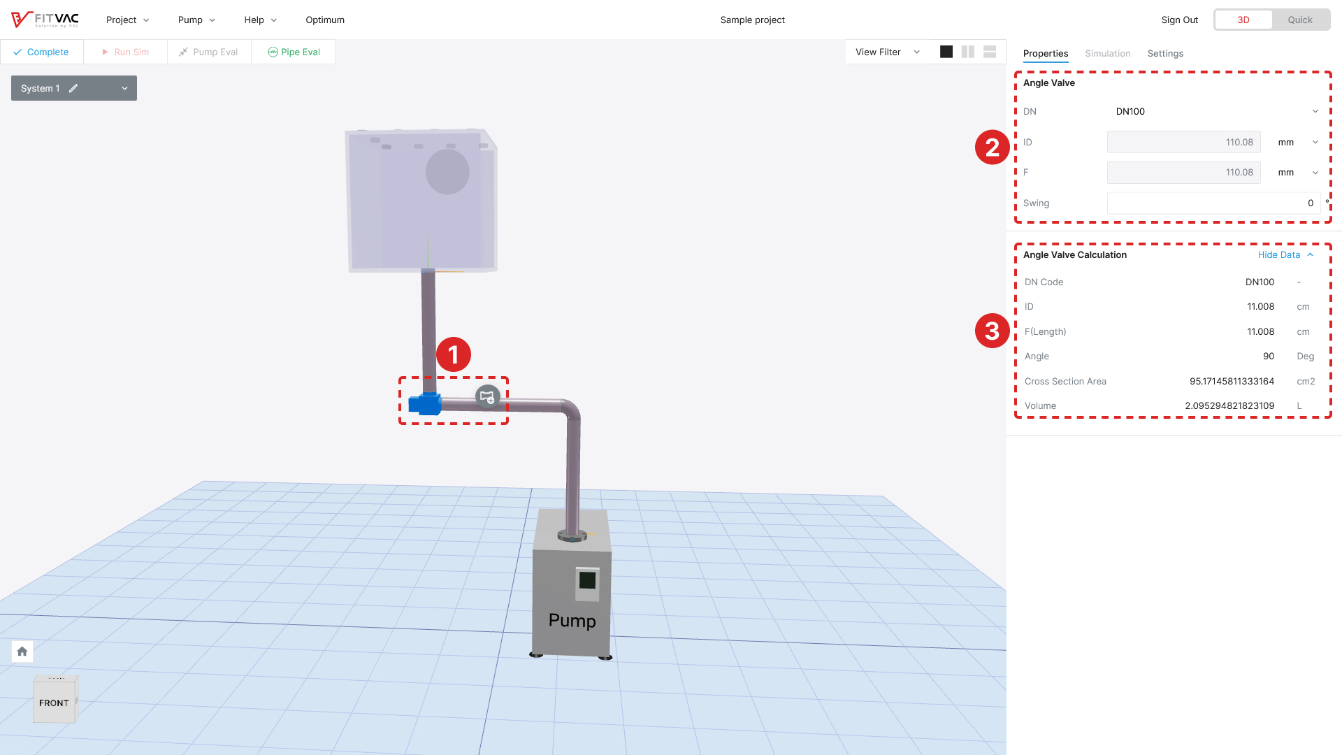
- Angle valve
- Select the first connected 90° Bend, Elbow, or Miter in the chamber and click the element menu button to replace it with an Angle valve
- Angle valve setting
- ID: Automatically set to the same ID from previous element
- Change ID: Select DN standard or select Custom to input numerical data directly
- Swing: Input the angle of the outlet direction (-360 < θ < 360)
- Angle valve and Bend, Elbow, Miter at 90° are interchangeable in modeling area (when pump connected)
- Angle valve detailed property
- Click the "Show keyboard_arrow_down" to display the angle valve's detailed property values
- The detailed property values of the angle valve are automatically set when changed in the ①
Pump Configuration

- Add the pump
- Click the "Add Pump" to select or import a pump to add
Pump Property
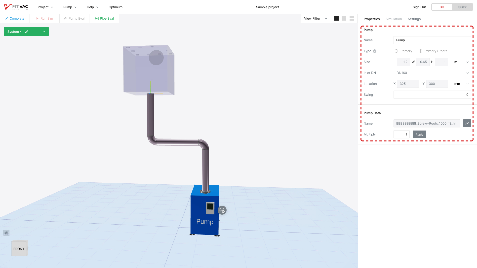
- Pump property values are displayed in the property window
- Pump name and swing can be changed in property window
- The other property of pump can be changed on the "Manage Pump…" menu → See Pump
Pump–Pipe Connection
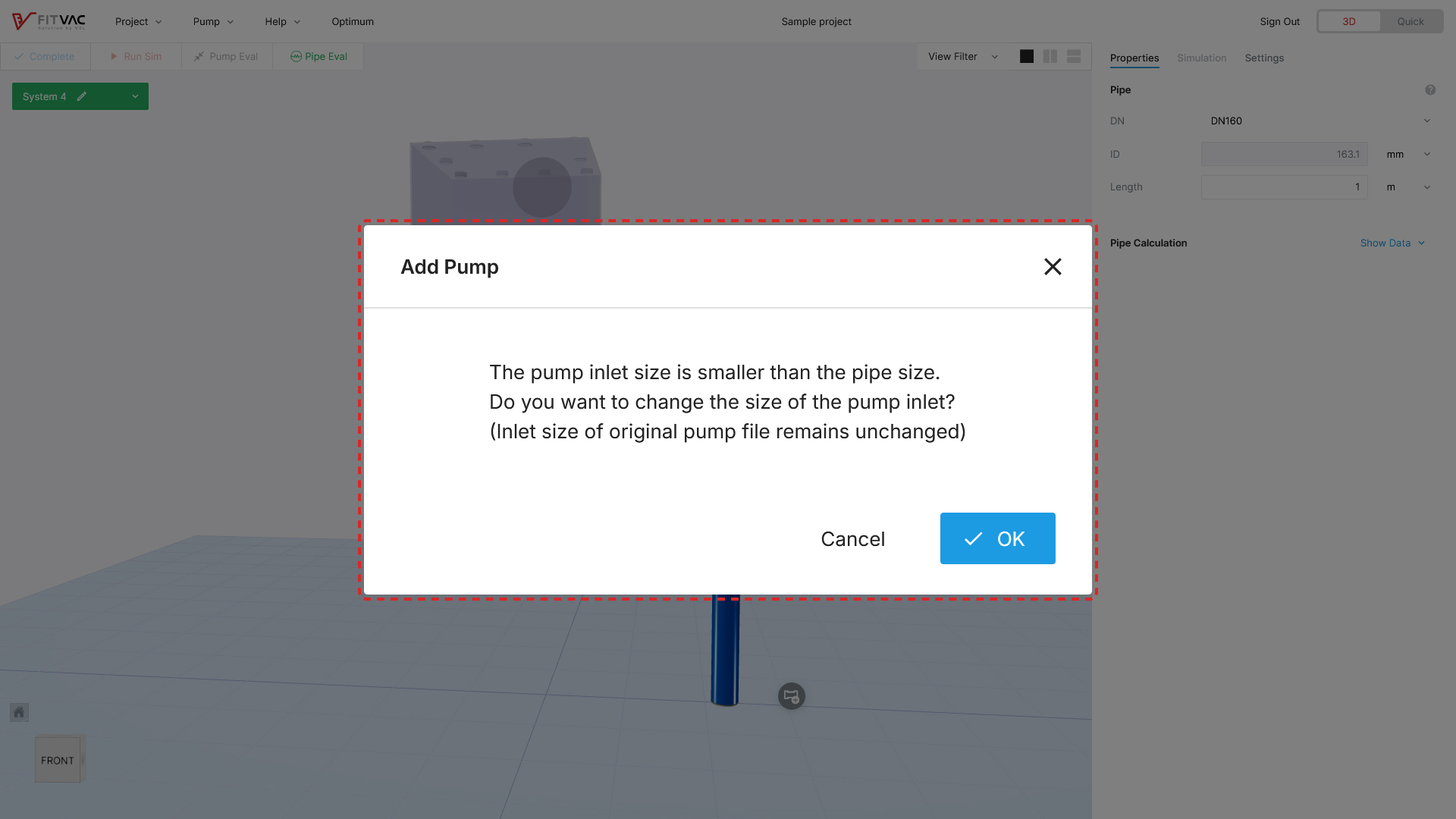
- When the pump Inlet ID is different from the pipe inlet ID, the pump Inlet ID changing message is displayed to window
- Click "Yes" to automatically adjust pump inlet ID
System Modeling Edit & Completion
System Modeling Edit
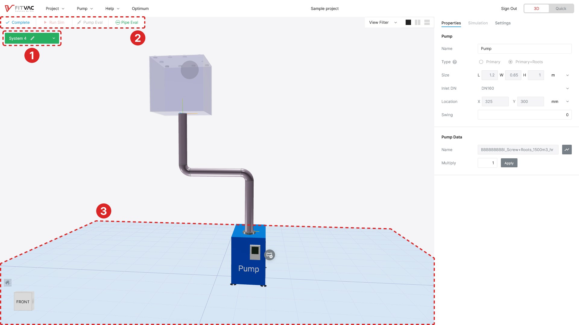

- System status: edit (Edit)
- System modeling is not completed (under configuring)
- Project menu in system edit

- Actived menu:
 Pipe Eval
 - Inactived menu: play_arrow Run Sim, close_fullscreen Pump Eval
- Pump Eval is available on the Plus plan and above, while CapaScan™ is available on the Optimum plan and above
- Actived menu:
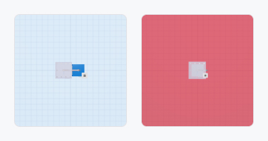
- In normal modeling state, bottom grid displayed as light blue
- In abnormal modeling state, bottom grid displayed as red
- The abnormal cases (system modeling cannot be completed)
- Physical interference between chamber–pipe–pump
- Pipe–Pump connection is not at a right angle
- Pump is separated from bottom grid
System Modeling Completion
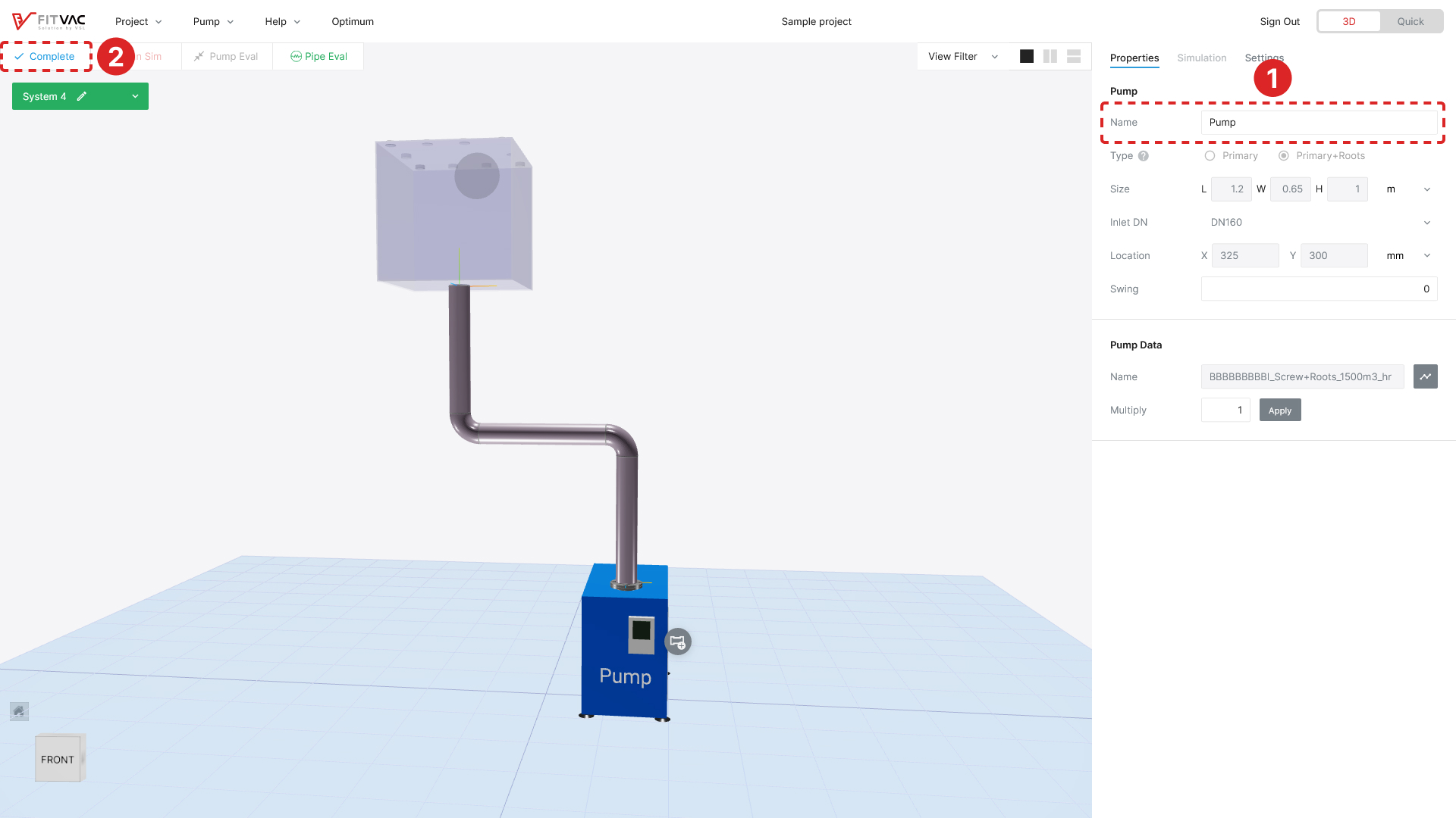
- Input pump name
- After uploading pump file, check Complete button activates when input the name in pump property
- Only Latin, numeric can be entered
- Enter up to 10 characters
- Project name can be duplicated
- System modeling completion
- Click the check Complete on the menu or "Complete System" on the element menu to complete the system modeling
- After complete the system modeling, the system is unchangeable
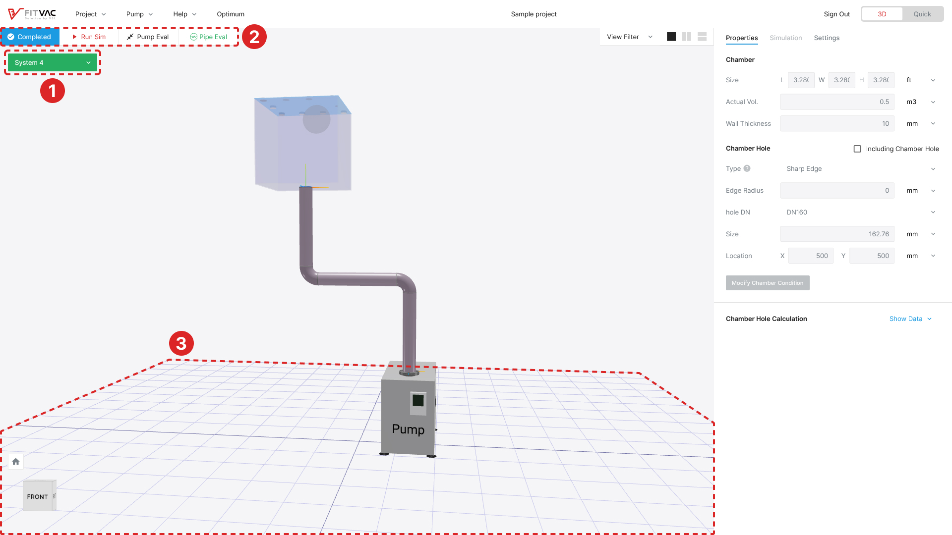

- The "edit" icon disappears when modeling for that system is complete (View state)
- Project menu in system complete

- Actived menu: play_arrow Run Sim, Pipe Eval, close_fullscreen Pump Eval
- Inactived menu: check_circle Completed
- Pump Eval is available on the Plus plan and above, while CapaScan™ is available on the Optimum plan and above
- Actived menu: play_arrow Run Sim,
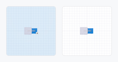
- In system completed state, the bottom grid color switched from light blue to transparent
System Creation, Editing, and Deletion
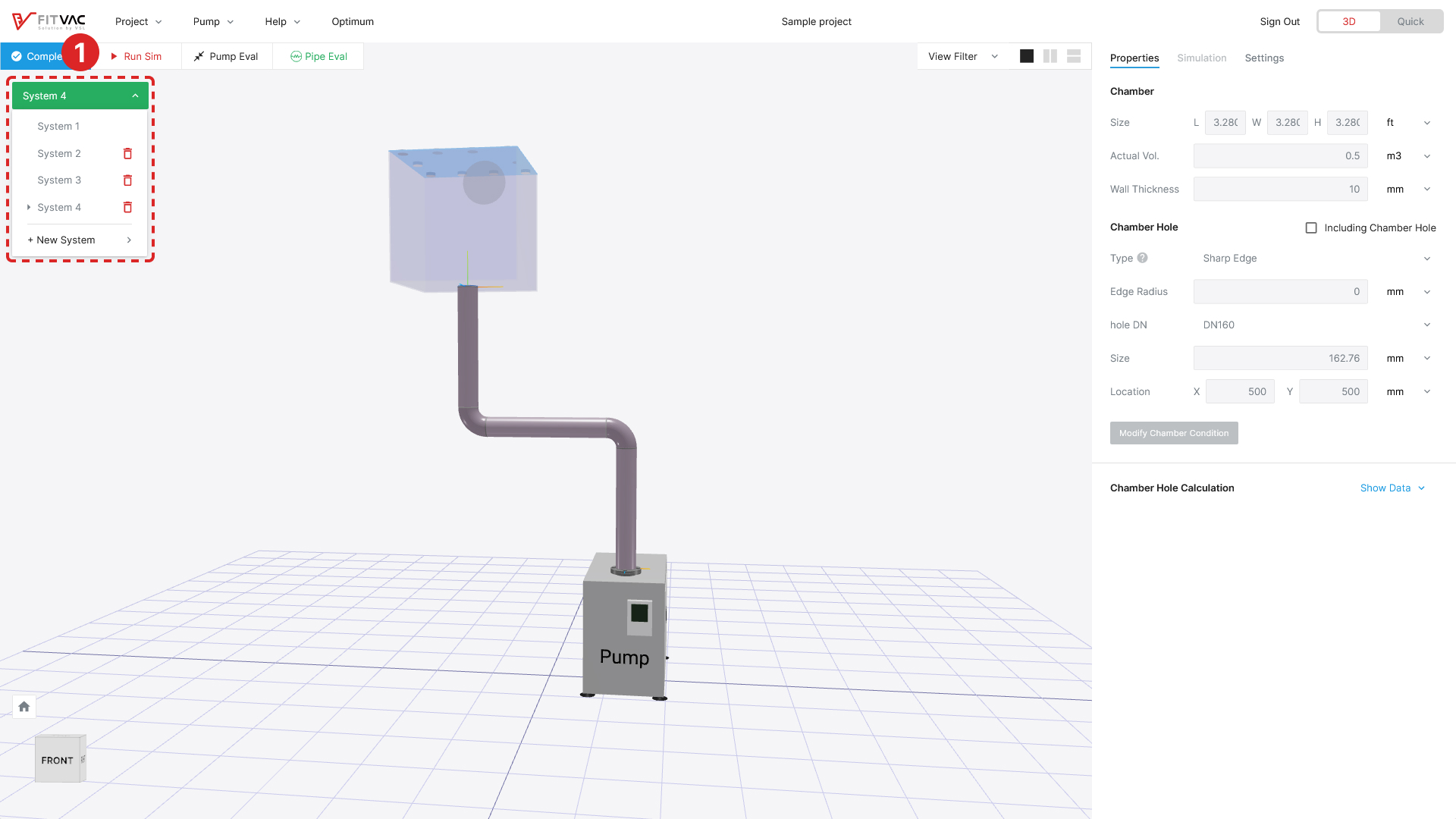
- System creation: Click the "+ New System" to add new system in the system list
- When system under editing exists, you cannot add a new system
- You can choose one of the completed systems to duplicate or add an empty one
- System deletion: Click the "delete" button to delete system (System deletion is only available on Optimum plan, and System 1 cannot be deleted)
- The number of available systems varies depending on your plan (Single: 1 / Twin: 2 / Plus: 3 / Optimum: 6)
System Comparison

- Select the system you want to compare from the list of systems in the split screen → See Screen View & Filter
System Simulation
- Click the play_arrow Run Sim button to see simulation charts appear on the right side of the screen
- PDT simulation → See Pump Down Time (PDT)
- F/P simulation → See Throughput (F/P)
- C simulation → See Conductance (C)
- Seff simulation → See Effective Pumping Speed (Seff)
- Click the
 Pipe Eval, HiPath™, and close_fullscreen CapaScan™ or close_fullscreen Pump Eval button to see evaluation
- Pipe Conductance Evaluation → See Pipe Evaluation and HiPath™
- Pump Capacity Evaluation → See CapaScan™ & Pump Capacity Evaluation
- Pipe Eval, HiPath™, and Pump Eval are available on the Plus plan and above; CapaScan™ is available on the Optimum plan and above